| English | 简体中文 | |||||||||
|
|||||||||
| Home | Product | Download | Support | Literature | Purchase | About Us | |||||||||
|
|
|||||||||
The
modal testing experiment presented here is performed by a medical system manufacturer using ModalVIEW software and National Instruments DSA hardware as the
modal testing and analysis tool. The
analysis result is used to verify noise and vibration performance of their structure design.
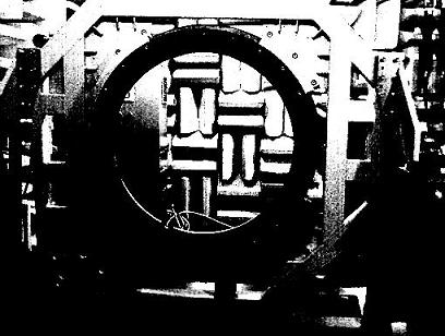 |
The structure of CT scanner is excited by impact hammer, and the vibraiton is measured using tri-axial accelerometer. ModalVIEW modal analysis software provides FRF measurement and advanced modal analysis
method based on mode stabilization diagram to extract modes from
FRF data. National Instruments 24-bit module USB-4431 is used to guarantee the
accurate measurement of weak vibration signal of measured points far away from
excitation point.
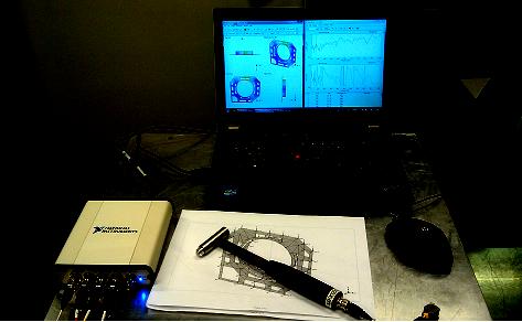 |
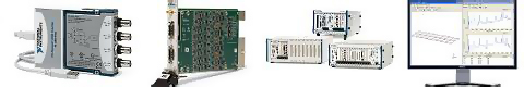
System configuration
In this modal testing experiment,
the following software and hardware are used:
1.ModalVIEW R2
Software.
2.NI
DSA System (USB-4431)
3.Tri-axial accelerometer (PCB 356A26).
4.Impact Hammer (PCB 086C01) .
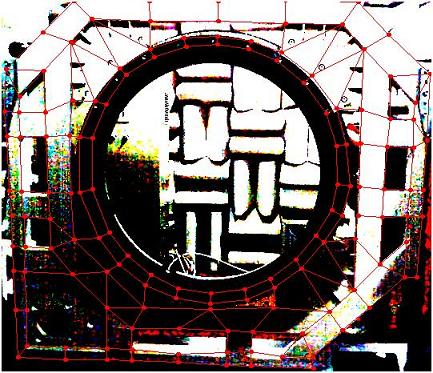
Structure Modeling
3D model of CT scanner structure is created from its photo. ModalVIEW helps to quickly create 2D grid from manually selected nodes on photo.
 |
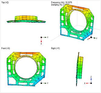
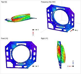
Analysis results
![]() Download this application note in
PDF format
Download this application note in
PDF format